Near hole Problem of multilayer PCB and PCB Troubleshooting
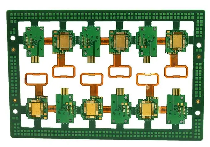
Multilayer PCB companies often encounter the problem of "hole to line is too close, whICh exceeds the process capability". When we design PCB boards, the most important consideration is how to connect each layer to the network signal line in the most reasonable way through wiring. The denser the lines of high-speed PCB are, the denser the vias (VIAs) are placed, and the vias can play the role of electrical connection between layers.
Then, what kind of difficulties will the near hole cause to the production? What near hole problems should we pay attention to? The following sections will tell you one by one.
If two holes are too close to each other during drilling operation, the efficiency of PCB drilling process will be affected. After the first hole is drilLED, the material on one side will be too thin when drilling the second hole, which will lead to uneven stress on the drill bit and uneven heat dissipation of the drill bit, resulting in broken drill bit, which will cause PCB hole collapse or missing holes without continuity.
2. The vias in the PC multilayer board will have hole rings on each layer of the circuit, and the surrounding environment of each layer of hole ring is different, with or without wire clamping. When optimizing documents, the CAM engineer of the Pcb factory will cut off a part of the hole ring when the wire clamp is too close or the hole is too close to the hole, so as to ensure that there is a safe distance of 3mil between the welding ring and different network copper/wire.
3. The hole position tolerance of the drilling is ≤ 0.05mm. When the tolerance goes to the upper limit, the following situations will occur in the multilayer plate:
(1) When the lines are dense, SMAll gaps occur irregularly 360 ° from vias to other elements. To ensure a safe distance of 3mil, the pad may be cut in multiple directions.
(2) According to the calculation of source file data, 6mil from hole edge to line edge, 4mil from hole ring, and 2mil from ring to line. To ensure a safety distance of 3mil from ring to line, 1mil welding ring needs to be cut, and only 3mil for pad after cutting. When the tolerance deviation of hole position is 0.05mm (2mil), there is only 1mil left for the hole ring.
4. PCB production will have a small amount of offset in the same direction, and the pad will be cut in an irregular direction. In the worst case, individual holes will cause broken solder rings.

5. Influence of inner layer pressing deviation of PCB multilayer board. Take a six ply board as an example, two core plates+copper foil are pressed together to form a six ply board. During pressing, core plate 1 and core plate 2 may have a deviation of ≤ 0.05mm when pressing, and the inner layer hole will also have an irregular deviation of 360 ° after pressing.
It can be concluded from the above problems that the PCB printing yield and PCB production efficiency are affected by the drilling process. If the hole ring is too small and there is no complete copper sheet protection around the hole, although the PCB can pass the open and short circuit test and there will be no problems in the early use of the product, the long-term use reliability is still insufficient.
Therefore, suggestions on hole to hole and hole to line spacing of multi-layer PCB and high-Speed PCB are given:
(1) Hole to wire to copper in Multilayer board:
4th floor: no pipe
6 layers: ≥ 6mil
8th floor: ≥ 7mil
10 layers or more: ≥ 8mil
(2) Clearance between inner diameter edges of vias:
Same network via: ≥ 8mil (0.2mm)
Via of different networks: ≥ 12mil (0.3mm)
Troubleshooting of PCB
The failure of a PCB is just like a bug encountered by a programmer. It is not as SIMple as making a board according to the process and printing components. The difficulty is a series of troubleshooting after the PCB is completed. Today's small editor will tell you about PCB troubleshooting.
Common PCB failures mainly focus on components, such as capacitors, resistors, inductors, diodes, triodes, FETs, etc. The integrated chips and crystal oscillators are obviously damaged, and judging these component failures can be observed through the eyes, which is more intuitive. There are obvious burning MARKs on the surface of the obviously damaged electronIC components. Such faults can be solved by directly replacing the defective components with new ones.
Not all PCB faults can be directly observed with eyes. Some faults can be found with specific tools for maintenance. Such as resistance, capacitance, diode and triode can not be seen from the surface. Common inspection uses include multimeter, capacitance meter, etc. If it is detected that the voltage or current of an electronic component is not within the normal range, it indicates that there is a problem with the component or the previous component. At this time, it is necessary to replace the component and recheck whether it is normal.
What should we do if we encounter a fault that cannot be detected by eyes or tools and the circuit board cannot work normally?
Many novices are helpless when they encounter this kind of problem. They can only do it again or change a board. In fact, in many cases, due to the coordination of various components during the installation process, the performance may be unstable, and further testing is required to decide whether to redo the board.
How to carry out the inspection? In this case, the instrument is obviously unable to help. We can try to judge according to the current and voltage, and try to narrow the possible range of faults. Experienced engineers may be able to quickly judge the fault area, but the specific component that is broken cannot be determined 100%. The only way is to try to replace the suspect component until the problem component is found.
As the carrier of components, PCB circuit board, in addition to electronic components, will also have failures. The most common example is the dead tin plating part. Due to process reasons, wire breakage may occur during PCB corrosion. If the fault cannot be repaired, the problem can only be solved with fine copper wire.
PCB manufacturers, PCB designers and PCBA manufacturers will explain the near hole problems of multilayer PCB boards and troubleshooting methods for PCB.


