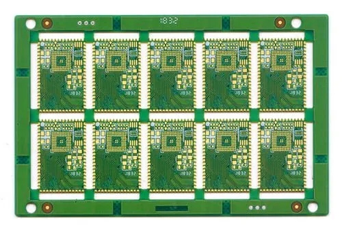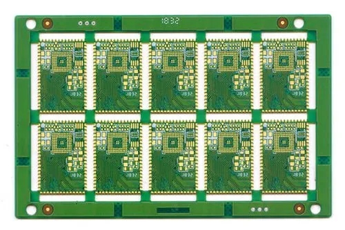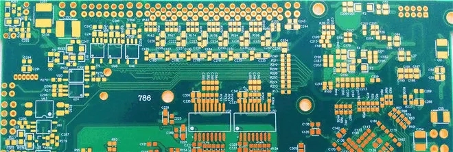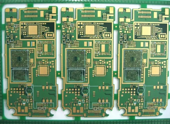
Let's learn about the causes and treatment of solder beads in pcb proofing
PCB proofing factor 1: the selection of solder paste directly affects the quality of welding
The metal content in the solder paste, the degree of oxidation of the metal powder, and the size of the metal powder can all affect the production of solder beads.
a. Metal content of solder paste
The mass ratio of the metal content in the solder paste is about 88%~92%, and the volume ratio is about 50%. When the metal content increases, the viscosity of solder paste increases, whICh can effectively resist the force generated by vaporization during preheating. With the increase of metal content, the metal powder is arranged closely, making it easier to combine without being blown away during melting. In addition, the increase of metal content may also reduce the "collapse" of solder paste after printing, so it is not easy to produce solder beads.
b. Oxidation degree of metal powder of solder paste
The higher the degree of oxidation of the metal powder in the solder paste, the greater the bonding resistance of the metal powder during welding, and it is not easy to soak between the solder paste and the bonding pad and components, thus reducing the solderability. The experiment proves that the occurrence rate of tin beads is proportional to the oxidation degree of metal powder. Generally, the degree of oxidation of solder in solder paste is controlLED below 0.05%, and the maximum limit is 0.15%
c. Size of metal powder in solder paste
The SMAller the particle size of the metal powder in the solder paste, the larger the overall surface area of the solder paste, resulting in a higher degree of oxidation of the finer powder, thus intensifying the phenomenon of solder beads. The experiment proves that tin beads are more likely to be produced when the solder paste with finer particles is selected.

D. Amount of flux in solder paste and activity of flux
Too much flux will cause local collapse of solder paste, which will make solder beads easy to produce. In addition, if the activity of the flux is too weak, the ability to remove oxidation is weak, and tin beads are more likely to be produced.
e. Other precautions
After the solder paste is taken out of the refrigerator, it is opened for use without being warmed up, which causes the solder paste to absorb water and generate solder beads due to splashing of solder paste during preheating; The PCB is affected with damp, the indoor humidity is too heavy, there is wind blowing against the solder paste, excessive diluent is added to the solder paste, and the machine stirring time is too long.
PCB proofing factor 2. fabrication and opening of steel mesh
a. Opening of steel mesh
We usually open the stencil according to the size of the pad. When printing solder paste, it is easy to print the solder paste on the solder mask, so that solder beads are generated during reflow soldering. Therefore, we open the steel mesh in this way. The opening of the steel mesh is 10% smaller than the actual size of the pad. In addition, we can change the shape of the opening to achieve the desired effect.
b. Thickness of steel mesh
The steel mesh Baidu is generally 0.12~0.17mm, and too thick will cause the "collapse" of solder paste, resulting in tin beads.
Pcb proofing factor 3. mounting pressure of mounting machine
If the pressure is too high during mounting, the solder paste will be easily squeezed onto the solder mask below the element, and the solder paste will melt and run around the element to form solder beads during reflow soldering. Solution: reduce the mounting pressure; Use appropriate steel mesh opening form to avoid solder paste being squeezed to the outside of the pad.
Pcb proofing factor 4. setting of furnace temperature curve
Tin beads are produced during reflow soldering. In the preheating stage, to make the temperature of solder paste, PCB and components rise to 120~150 ℃, the thermal shock of components during reflow must be reduced. In this stage, the flux in the solder paste starts to vaporize, so that small particles of metal powder run separately to the bottom of the components, and run around the components to form solder beads during reflow. At this stage, the temperature shall not rise too fast, generally less than 2.5 ℃/S, which may easily cause solder spatter and form solder beads. Therefore, the preheating temperature and speed of reflow soldering should be adjusted to control the production of solder beads.
PCB manufacturers, PCB designers and PCBA manufacturers will explain the causes and treatment of solder beads produced by pcb proofing.


