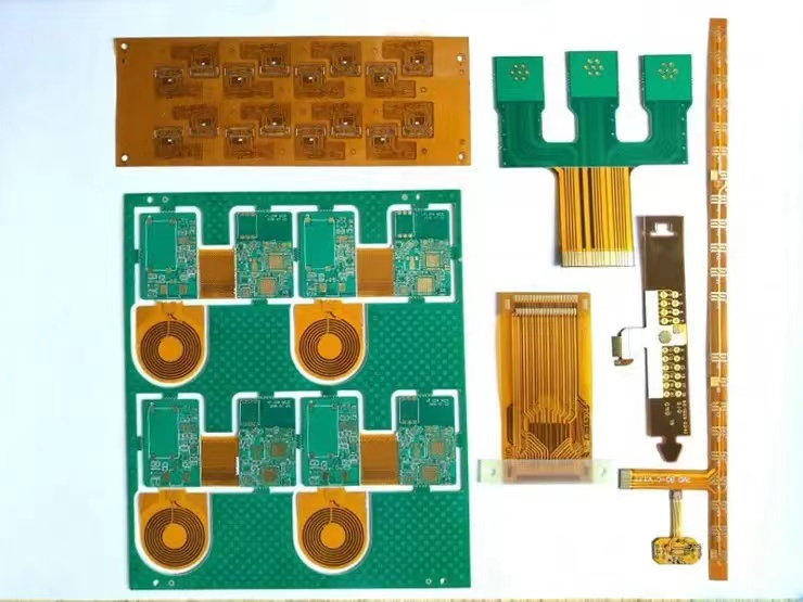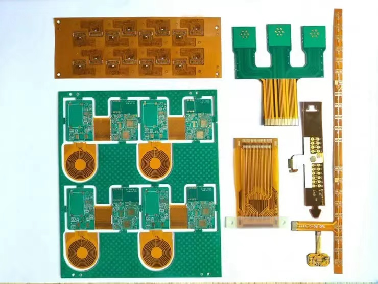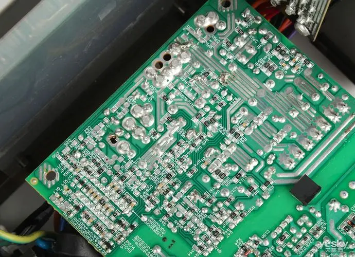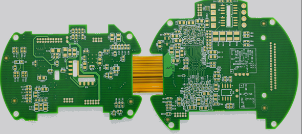
Pretreatment of FPC Electroplating The exposed copper conductor surface of FPC after the coating process may be contaminated by adhesive or ink, as well as oxidation and discoloration caused by high-temperature process. To obtain a tight coating with good adhesion, the contamination and oxide layer on the conductor surface must be removed to make the conductor surface clean. However, some of these pollutions are firmly bound to the copper conductor and cannot be completely removed with a weak cleaning agent. Therefore, most of them are treated with alkaline abrasives and polishing brushes with a certain strength. Most of the coating adhesives are epoxy resins with poor alkali resistance, whICh will lead to a decline in the bonding strength. Although it is not obvious, the plating solution may infiltrate from the edge of the coating in the FPC electroplating process, In severe cases, the covering layer will peel off. In the final welding, the solder drill gets under the coating. It can be said that the pre-treatment cleaning process will have a significant impact on the basic characteristics of the flexible printed circuit board F {C, and the treatment conditions must be given full attention.

Thickness of FPC electroplating When electroplating, the deposition speed of the plated metal is directly related to the electric field strength, which changes with the shape of the line graph and the position of the electrode. Generally, the thinner the wire width is, the sharper the terminal at the terminal is, the closer the distance to the electrode is, the greater the electric field strength is, and the thicker the coating at this position is. In the applications related to flexible printed circuit boards, there are many wire widths in the same line that are greatly different, which is more likely to cause uneven coating thickness. To prevent this, a shunt cathode pattern can be attached around the line to absorb the uneven current distributed on the electroplating pattern, and maximize the uniformity of coating thickness on all parts. Therefore, efforts must be made on the electrode structure. A compromise scheme is proposed here. The standard for the parts with high requirements for uniformity of coating thickness is strict, and the standard for other parts is relatively relaxed, such as the standard for molten solder plating, gold plating layer for metal wire overlap (welding), etc., is higher, while the requirement for coating thickness of lead tin for general anti-corrosion is relatively relaxed.
The SMEars and dirt of FPC electroplating are just in the plating state. Especially, there is no problem with the appearance. However, some surfaces appear smears, dirt, discoloration and other phenomena shortly after. In particular, no abnormality is found during the factory inspection. However, when the user conducts acceptance inspection, there is a problem with the appearance. This is due to insufficient drifting, and there is residual plating solution on the coating surface, which is caused by chEMIcal reaction slowly after a period of time. Especially for flexible printed boards, due to their softness and unevenness, various solutions are easy to accumulate in the recesses, which will react and change color in this part. In order to prevent this situation, not only full drifting, but also full drying treatment should be carried out. It can be confirmed whether drift charging is carried out through high temperature thermal aging test


