In order to keep consistent with the PCR clock of satellite or cable digital TV network, the master clock will generally use a "VCXO" (voltage controlLED crystal oscillator) with a center frequency of 27Mhz, whICh can control the PCB voltage to adjust the frequency in a SMAll range. The center frequency is the midpoint of the VCXO output frequency range. The traction range is the ratio of change frequency (increase or decrease) to center frequency. This ratio is generally expressed in ppm (one millionth), representing the relative frequency traction range of VCXO. Generally, the traction range is about 100 - 200ppm. VCXO clock (CLK) generator has been applied in many PCB systems, such as digital TV, digital audio, ADSL and STB.

If the clock of the (satellite) broadcast network is greater than 27M at a certain time (e.g. 27.123Mhz), the CPU of the set-top box board will output a variable voltage according to the PCR jitter, and control the VCXO to output the clock synchronized with the network (e.g. 27.123Mhz). In this way, the video and audio buffers inside the set-top box board will not overflow or be out of sync due to clock jitter.
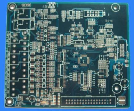
Set top box board
The selection and layout of crystals will have a certain impact on the performance parameters of VCXO CLK generator. When selecting crystals, in addition to frequency, package, accuracy and operating temperature range, equivalent series resistance and load capacitance should also be paid attention to in VCXO applications. The series resistance increases the power consumption of the crystal. The lower the PCB resistance, the easier the oscillator starts. When the load capacitance is small, the tuning range of VCXO is limited to the upper end; SIMilarly, when the capacitance value is large, the tuning range will be limited to the lower end.
The digital TV network itself will generate the whole network clock jitter of the PCR, and the VCXO clock generator inside the set-top box board is designed to adapt to this jitter. VCXO also has jitter problem. We try to choose VCXO with low jitter under the prEMIse of considering the cost. Designers should distinguish between these two "jitter" concepts.
Since set-top box boards and PC host boards need to provide a variety of peripheral interface circuits, such as USB, ethernet, etc., there is an increasing demand for a variety of clock frequencies. There are often nearly ten clock frequencies on a board. Therefore, the clock circuit of the main board must provide various operating frequencies for these many PCB components.
In the past, the old motherboard used quartz oscillator to process, but the quartz oscillator can only output one frequency at a time. It is obviously not enough for new mainboards that require multiple clock outputs. Therefore, some operators integrate these oscillatory circuits originally scattered on the motherboard into a PCB chip that can output various frequencies. The motherboard can save cost and space by using such clock to generate chips.
The multi-channel clock chip only needs an external quartz crystal to provide a reference frequency, and its internal PLL and frequency division circuit can generate clock outputs of various frequencies to replace multiple quartz crystals in the traditional system.


