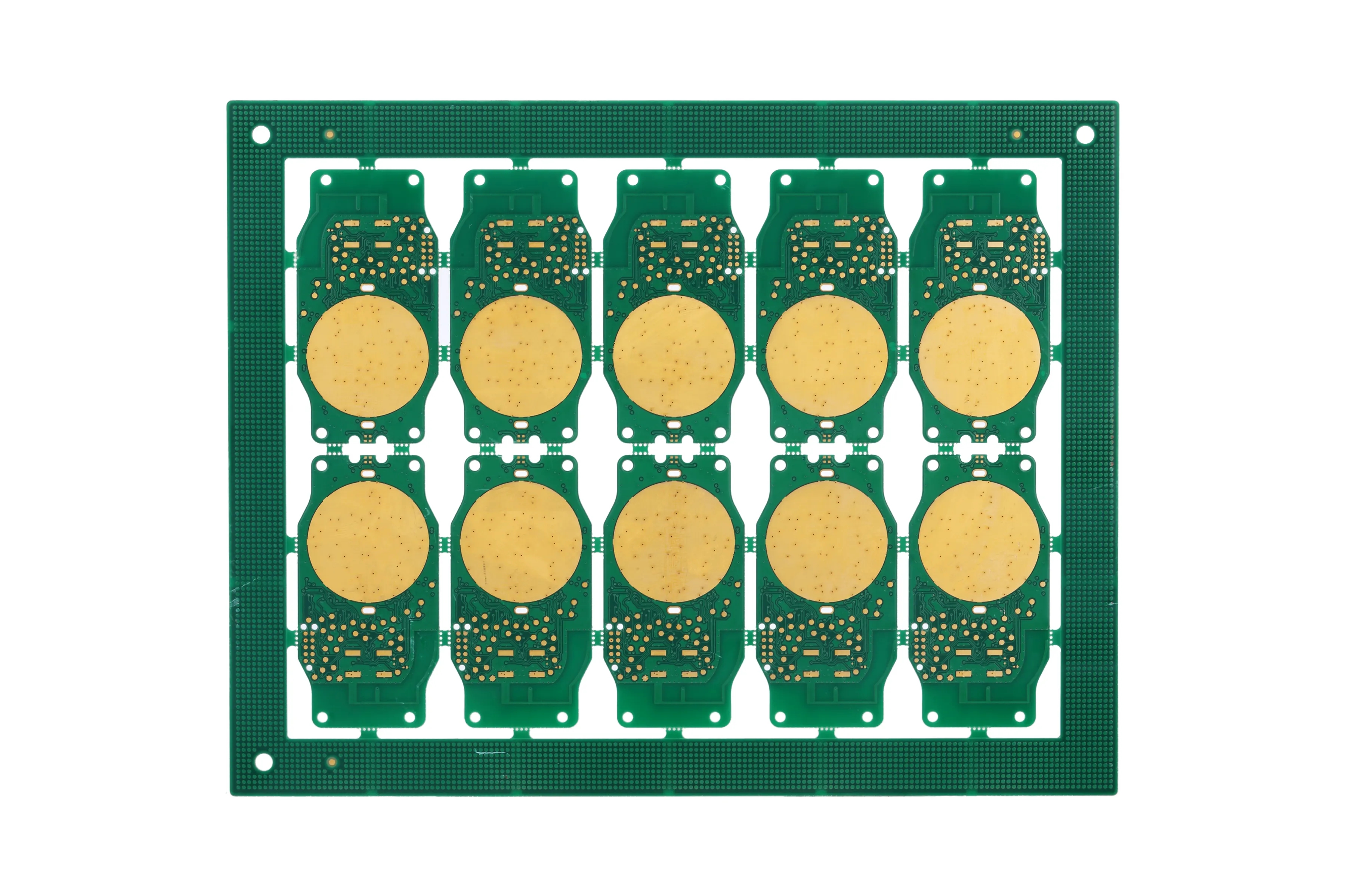
PCB manufacturer: PCB design skills and specifICations for LED drive power supply
In any power supply design, the physical design of PCB is the last link. Its design method determines the electromagnetic interference and power supply stability. Let's analyze these links specifically:
1、 The design process from schematic diagram to PCB establishes component parameters ->Input schematic network table ->Design parameter setting ->Manual layout ->Manual wiring ->Validate design ->Review ->CAM output.
2、 The spacing between adjacent conductors in parameter setting must meet the electrical safety requirements, and the spacing should be as wide as possible to facilitate operation and production. The minimum spacing shall be at least suitable for the voltage to be borne. When the wiring density is low, the spacing of signal lines can be appropriately increased. The signal lines with high and low level differences shall be as short as possible and the spacing shall be increased. Generally, the wiring spacing is set to 8mil.
The distance from the edge of the inner hole of the pad to the edge of the printed board shall be greater than 1mm, so as to avoid pad defects during processing. When the wiring connected with the pad is thin, the connection between the pad and the wiring should be designed as a water drop. This has the advantage that the pad is not easy to peel, but the wiring and the pad are not easy to disconnect.

3、 The practice of component layout has proved that even if the circuit schematic diagram is correctly designed and the printed circuit board is improperly designed, the reliability of electronic equipment will be adversely affected. For example, if two thin parallel lines of the printed board are close together, the delay of the signal waveform will be formed and the reflected noise will be formed at the end of the transmission line; The interference caused by improper consideration of power supply and ground wire will degrade the performance of the product. Therefore, correct methods should be used when designing printed circuit boards.
4、 The wiring switching power supply contains high-frequency signals. Any printed wire on the PCB can act as an antenna. The length and width of the printed wire will affect its impedance and inductance, thus affecting the frequency response. Even the printed wire passing through the DC signal will be coupled to the RF signal from the adjacent printed wire and cause circuit problems (or even radiate interference signals again).
5、 After checking the wiring design, it is necessary to carefully check whether the wiring design conforms to the rules formulated by the designer, and also to confirm whether the rules formulated conform to the requirements of the production process of printed boards. Generally, it is necessary to check whether the distances between lines, lines and component pads, lines and through holes, component pads and through holes, through holes and through holes are reasonable and meet the Production requirements. Whether the width of the power line and ground wire is appropriate, and whether there is a place in the PCB where the ground wire can be widened. Note: Some errors can be ignored. For example, some parts of the Outline of some connectors are placed outside the board frame, and errors will occur when checking the spacing; In addition, every time the routing and vias are modified, they should be copper coated again.
6、 Recheck according to the "PCB checklist", including design rules, layer definition, line width, spacing, pad and via settings, and focus on the rationality of device layout, routing of power supply and ground wire networks, routing and shielding of high-speed clock networks, and placement and connection of decoupling capacitors.
PCB manufacturers, PCB designers and PCBA manufacturers will explain the PCB design skills and specifications of LED driver power supply.


