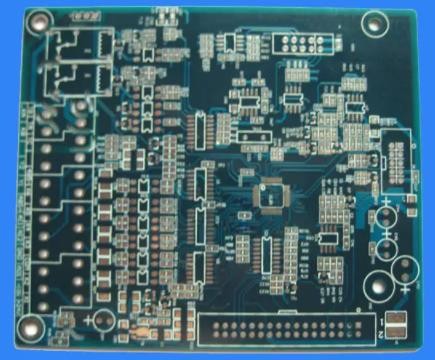
At the beginning, the design of IoT products needs to be improved in many aspects. IoT equipment integrates mobility, low power consumption, RF communICation, mixed signal function and high-speed data transmission function into a SMAll space. Keeping all these factors in mind will help you design correctly in the first place.
PCB industry standard
If you intend to eventually bring new equipment to the PCB market, the equipment must meet or exceed many PCB industry standards. These standards specify several operational requirements to ensure compatibility between devices built by others and devices built by others. It is important to get familiar with and work according to industry standards as early as possible. If you can design equipment that meets the standards now, you do not need to redesign it later.
IPC standards are a good starting point, and these standards will be often referred to in the design process. For example, IEEE, ISO and ANSI also specify PCB operation standards. When you start to study industry standards, it seems difficult to understand. No one can remember all PCB design standards, so it is important to focus on the standards applicable to devices.
IoT applications and low-power design

Not all IoT devices can be plugged into wall sockets. If the equipment is designed to be mobile, learn about designing the equipment to use as little power as possible. Mobile IoT devices may operate in a variety of different modes, including sleep, standby, burst, etc. The best way to save battery power and ensure the reliability of each mode is to turn off unnecessary parts of the device when they are not needed.
It is better to consider the power consumption in PCB, because it occurs in different function blocks on the board. It is better to divide the PCB into functional blocks and allocate the power budget for each block. If you encounter power consumption problems, you can consult the component vendor. They can recommend alternative components with lower power consumption and keep costs within budget.
IoT devices will also require a memory module that will consume energy. Selecting the right memory to meet functional requirements can keep power consumption within budget. Each type of memory has its advantages and disadvantages. For example, if DMA is selected instead of DRAM, you can save power, but increase latency and throughput. As a designer, you need to weigh the advantages and disadvantages of each type of memory.
PCB design of Internet of Things
Keep the device in touch with RF design
Unless you plan to plug the IoT device directly into the Ethernet port, the device will connect to the Internet wirelessly through WiFi. Bluetooth may also be available, especially if the device is intended to interface with the phone. Many other wireless networking protocols are used to send and receive information using RF signals. If you are not familiar with various wireless protocols, that is a good way.
The government manages the allocation of radio spectrum and allocates certain frequency bands for different purposes. For example, WiFi signals operate at 2.4 GHz, while other RF protocols will operate at different frequencies in the RF spectrum. Industry standards also specify design constraints to help ensure that the design works correctly.
The good news is that you don't have to design RF modules from scratch. Off the shelf wireless modules that meet industry standards can be purchased from electronic suppliers and easily integrated into the design. These components can reduce the overall dimensions while still including all the required functions.
Mixed signal design
Many IoT devices, especially mobile phones and devices for smart homes, will operate using many sensors that enable the device to interact with the world around it. Sensor outputs in IoT devices must be converted into analog signals of digital signals. Once converted into digital signals, digital data can be encoded and manipulated just like any other digital data set.
Due to the increasing amount of data being processed by IoT devices, PCB processors must move data between components at a higher speed. The layout will need to consider issues such as crosstalk, clock skew, propagation delay, attenuation, and impedance matching. Mixed high-speed digital and analog signals also require that the analog and digital parts of the board be separated in different parts of the board.
Proper SIMulation protocols can ensure accuracy in IC and behavior construction macro modeling. Use the powerful SPICE emulator to ensure PCB security.
Simulation, smaller circuit board, higher component density
If you have been required to comply with power requirements and mixed signal protocols, such as packaging all RF modules, logic ICs, power management components, microprocessors, cabling, memory, displays, charging/USB ports and other electronIC components, it feels like a Tetris game. Every inch of space is precious. If you want to make full use of equipment, you need to make full use of all spaces.
However, there is no need to manage each factor separately. With appropriate SPICE simulations, it will be possible to track power efficiency, design vulnerabilities, analyze impedance, and determine the necessary boundary dimensions. The SPICE library can be very helpful for analysis. It will have easy to access component parameter integration and modeling, as well as templates for building custom models from it.


