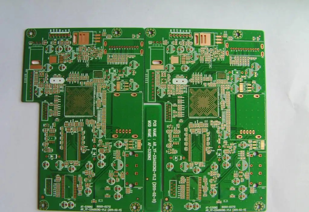
DetaiLED introduction of COB customization process
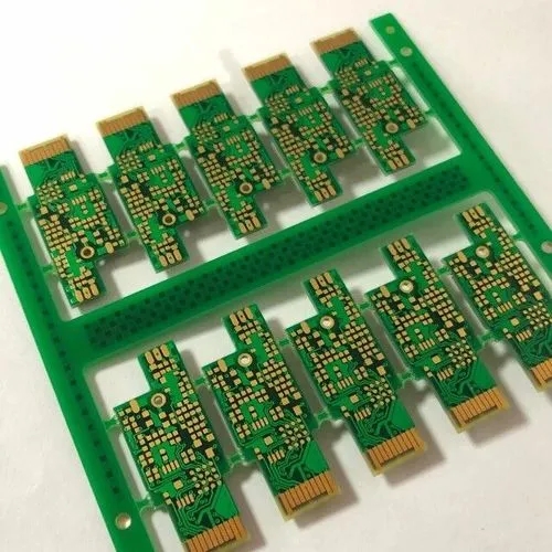
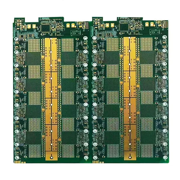
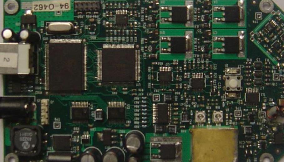
COB (Bonding): Bonding is a transliteration of English "bonding", whICh is a wiring method in chip production process. It is generally used to connect the internal circuit of the chip with the packaging pin with gold wire before packaging. Generally, after bonding (that is, after the circuit is connected with the pin), the chip is packaged with black gel, and the advanced external packaging technology COB is used. The process of this process is to implant the tested wafer on the special circuit board, then connect the wafer circuit to the circuit board with gold wire, and then cover the melted organic materials with special protection functions on the wafer to complete the post packaging of the chip.
COB process flow and basic requirements
Cleaning PCB -- dripping adhesive -- chip pasting -- testing -- heating and curing of black sealing adhesive -- testing -- warehousing
1. Clean PCB
The cleaned PCB board still has oil stain or oxide layer and other dirty parts. Use a skin rub to test the upper and position or a test pin to clean the cleaned PCB board with a brush or blow it with an air gun before it can enter the next process. Ion dust blower shall be used for products with strict anti-static property. The purpose of cleaning is to remove the dust and oil dirt on the bonding wire pad of PCB board to improve the bonding quality.
2. Drop adhesive
The purpose of dropping adhesive is to prevent the DIE from falling off during product transmission and bonding
Needle transfer and pressure injection are usually used in COB process
Needle transfer method: use a needle to take a SMAll drop of adhesive from the container and apply it on the PCB, which is a very fast dispensing method
Pressure injection method: put the glue into the syringe, and apply a certain amount of air pressure to squeeze the glue out. The size of the glue point depends on the size of the injector nozzle diameter, the pressure time and the pressure, and is related to the viscosity. This process is generally used on the drip stick machine or DIE BOND automatic equipment
The size and height of glue drops depend on the type, size, distance from PAD bit and weight of the chip (DIE). The chip adhesive drops with large size and weight are larger, and should not be too large to ensure sufficient viscosity. At the same time, the adhesive should not pollute the bonding pad of the bond line. If there is any standard, it can only be determined according to different products. It is not necessary to take what cannot exceed 1/3 of the height of the chip and how much glue cannot be exposed as the standard.
3. Chip pasting
Chip pasting is also called DIE BOND (solid crystal) pasting DIE State, DIE State IC and other companies have different names. In chip pasting, the material hardness of the vacuum suction pen (suction nozzle) is required to be small (some companies use cotton swab for pasting). The diameter of the suction nozzle depends on the chip size, and the nozzle tip must be flat to avoid scratching the DIE surface. When pasting, check the model of the DIE and PCB, and whether the pasting direction is correct. The DIE towel must be "smooth and straight" and "flat" from the DIE towel to the PCB, which means that the DIE is parallel to the PCB and there is no virtual position. "stable" means that the batch of DIE and PCB are not easy to fall off in the whole process. Be sure to note that the direction of the chip (DIE) must not be stuck in the opposite direction.
4. State line (lead wire bonding)
State line (lead wire bonding) The name of the wire bond connection varies. Take the state connection as an example
Bonding connects the two welding points of each state line according to the location specified in the Bonding diagram to make it electrically and mechanically connected. When conducting bond tension test on PCB, it is required that the tension of bond tension shall comply with the standard set by the company (reference line 1.0 is greater than or equal to 3.5G, line 1.25 is greater than or equal to 4.5G). The shape of aluminum wire solder joint is elliptical, and the shape of gold wire solder joint is spherical.

Standard for Bonding Melting Point
aluminum steel:
Wire tail is greater than or equal to 0.3 times of wire diameter is less than or equal to 1.5 times of wire diameter
The length of solder joint is greater than or equal to 1.5 times of wire diameter, less than or equal to 5.0 times of wire diameter
The width of solder joint is greater than or equal to 1.2 times of wire diameter, less than or equal to 3.0 times of wire diameter
The height of the line arc is equal to the parabolic height of the circle (not too high or too low, depending on the product)
Gold thread:
Welding ball is generally about 2.6-2.7 times of wire diameter
The bonding process shall be handled with care, and the points shall be accurate. The operator shall observe the bonding process with a microscope to see if there are any bad phenomena such as broken wires, coiled wires, deflection, cold and hot welding, aluminum peeling, etc. If there are any, the manager or technician shall be notified immediately. Before formal production, there must be a specially assigned person for the first inspection to check whether there is any fault, lack of state, missing state tension, etc. A specially assigned person shall check the correctness every 2 hours.
5. Sealing glue
Sealing glue is mainly used to apply black glue to PCB boards that are tested OK. During dispensing, it should be noted that the black glue should completely cover the PCB solar circle and the bonding chip aluminum wire, and there should be no dew. The black glue should also not seal the solar circle and other places with black glue. If there is glue leakage, it should be wiped off immediately with a cloth strip. During the whole dispensing process, the needle tip or the hair stick shall not touch the DIE and the fixed line. The dried black glue surface shall be free of air holes and uncured black glue. The height of black glue should not exceed 1.8mm, and it is specially required that it should be less than 1.5mm. The temperature of preheating plate and drying temperature should be strictly controlled during dispensing. (Take the BE-08 black glue FR4 PCB board as an example: preheating temperature is 120 ± 15 ° C, time is 1.5-3.0 minutes, drying temperature is 140 ± 15 ° C, time is 40-60 minutes) Needle transfer method and pressure injection method are also commonly used for sealant sealing. Some companies also use the glue drip machine, but its cost is high and its efficiency is low. Generally, cotton swabs and syringes are used to drip glue, but the operators should have skilled operation ability and strict process requirements. If the chip is damaged, it will be very difficult to repair it. Therefore, the management personnel and engineering personnel of this process must be strictly controlled.
6. Testing
In the bonding process, there will be some undesirable phenomena, such as wire breakage, wire winding, false soldering, which will lead to chip failure, so chip level packaging must undergo performance testing
According to the detection methods, it can be divided into two categories: non-contact detection (inspection) and contact detection (testing). The non-contact detection has developed from manual visual inspection to automatic optical image analysis (AOI) X-ray analysis, from appearance circuit graphic inspection to inner layer solder joint quality inspection, and from independent inspection to the combination of quality monitoring and defect repair.
Although the bonding machine is equipped with the automatic welding line quality detection function (BQM), the automatic welding line quality detection of the bonding machine mainly adopts two methods: design rule detection (DRC) and figure recognition. DRC checks the welding line quality according to some given rules, such as how much the melting point is less than or more than the wire diameter. The pattern recognition method is to compare the stored digital image with the actual work. But this is affected by process control, process procedures, parameter changes, etc. The specific method shall be determined according to the specific conditions of each unit's production line and products. However, no matter what conditions are available, visual inspection is the basic inspection method and one of the contents that COB technologists and inspectors must master. The two should complement each other and cannot replace each other.
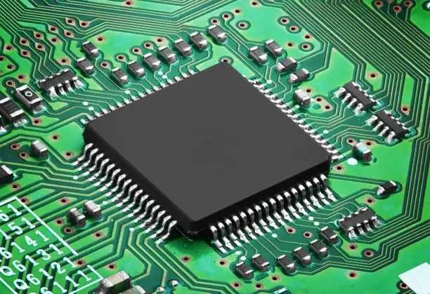
Cob (Chip On Board), also known as chip direct mounting technology, is to directly bind and mount the bare die of integrated circuit chip on the circuit board by using adhesives or automatic tape welding, wire welding, flip chip welding and other methods.
Advantages of COB technology:
1. Better performance: Cob technology is used to bind the chip bare die directly to the pcb board, eliminating the requirement for lead wire bonding, increasing the connection density of input/output (I/O), and making the product performance more reliable and stable.
2. Higher integration: Cob technology is adopted to eliminate the link pins between the chip and the application circuit board and improve the product integration.
3. Smaller volume: Cob technology is adopted. Because it can be bound and mounted on both sides of the pcb, the volume of the cob application module is reduced accordingly, and the application space of the cob module is expanded.
4. More ease of use and SIMpler product process flow: the original cluster bus technology is adopted, and pins are used between the cob board and the application board to facilitate interconnection, eliminating the welding process that must be used to use the chip, reducing the difficulty of product use, simplifying the product process, making the product easier to replace, and enhancing the product usability.
5. Lower cost: Cob technology is directly bound and packaged on the pcb board, which eliminates the cost of the chip in the process of planting balls, welding, etc., and the design of the user board is simpler, which can be realized only by a single layer of board, effectively reducing the cost of embedded products.


